There are 2 type of Stepper Motor;
- Bipolar Stepper Motor
- Unipolar Stepper Motor
Unipolar Stepper Motors
The unipolar stepper motor has five or six wires
and four coils (actually two coils divided by center connections on each coil).
The center connections of the coils are tied together and used as the power
connection. They are called unipolar steppers because power always comes in on
this one pole.
Bipolar stepper motors
The bipolar stepper motor usually has four wires
coming out of it. Unlike unipolar steppers, bipolar steppers have no common
center connection. They have two independent sets of coils instead. You can
distinguish them from unipolar steppers by measuring the resistance between the
wires. You should find two pairs of wires with equal resistance. If you’ve got
the leads of your meter connected to two wires that are not connected (i.e. not
attached to the same coil), you should see infinite resistance (or no
continuity).
Like other motors, stepper motors require more
power than a microcontroller can give them, so you’ll need a separate power
supply for it. Ideally you’ll know the voltage from the manufacturer, but if
not, get a variable DC power supply, apply the minimum voltage (hopefully 3V or
so), apply voltage across two wires of a coil (e.g. 1 to 2 or 3 to 4) and
slowly raise the voltage until the motor is difficult to turn. It is possible
to damage a motor this way, so don’t go too far. Typical voltages for a stepper
might be 5V, 9V, 12V, 24V. Higher than 24V is less common for small steppers,
and frankly, above that level it’s best not to guess.
To control the stepper, apply voltage to each of
the coils in a specific sequence. The sequence would go like this:
|
Step
|
wire 1
|
wire 2
|
wire 3
|
wire 4
|
|
1
|
High
|
low
|
high
|
low
|
|
2
|
low
|
high
|
high
|
low
|
|
3
|
low
|
high
|
low
|
high
|
|
4
|
high
|
low
|
low
|
high
|
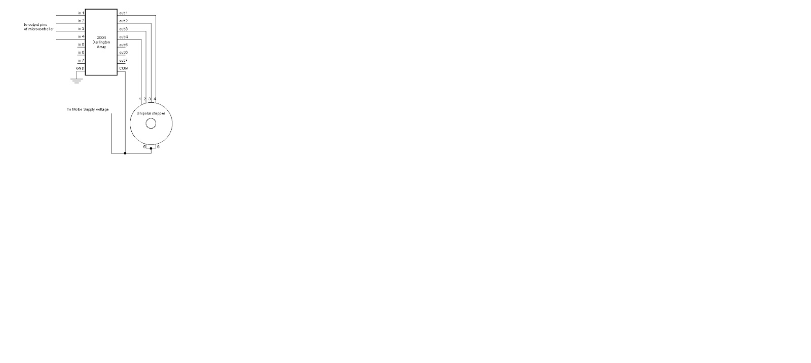
To control a unipolar stepper, you use a Darlington
Transistor Array. The stepping sequence is as shown above. Wires 5 and 6 are
wired to the supply voltage.
To control a bipolar stepper motor, you give the
coils current using to the same steps as for a unipolar stepper motor. However,
instead of using four coils, you use the both poles of the two coils, and
reverse the polarity of the current.
The easiest way to reverse the polarity in the
coils is to use a pair of H-bridges. The L293D dual H-bridge has two H-bridges
in the chip, so it will work nicely for this purpose.
Once you have the motor stepping in one direction,
stepping in the other direction is simply a matter of doing the steps in
reverse order.
Knowing the position is a matter of knowing how
many degrees per step, and counting the steps and multiplying by that many
degrees. So for examples, if you have a 1.8-degree stepper, and it’s turned 200
steps, then it’s turned 1.8 x 200 degrees, or 360 degrees, or one full
revolution.
Two-Wire Control
Thanks to Sebastian Gassner for ideas on how to do
this.
In every step of the sequence, two wires are always
set to opposite polarities. Because of this, it’s possible to control steppers
with only two wires instead of four, with a slightly more complex circuit. The
stepping sequence is the same as it is for the two middle wires of the sequence
above:
|
Step
|
wire 1
|
wire 2
|
|
1
|
low
|
high
|
|
2
|
high
|
high
|
|
3
|
high
|
low
|
|
4
|
low
|
low
|
The circuits for two-wire stepping are as follows:
Unipolar stepper two-wire circuit:
Biolar stepper two-wire circuit:
Programming the Microcontroller to Control a
Stepper
Because both unipolar and bipolar stepper motors
are controlled by the same stepping sequence, we can use the same
microcontroller code to control either one. In the code examples below, connect
either the Darlington transistor array (for unipolar steppers) or the dual
H-bridge (for bipolar steppers) to the pins of your microcontroller as
described in each example. There is a switch attached to the microcontroller as
well. When the switch is high, the motor turns one direction. When it’s low, it
turns the other direction.
The examples below use the 4-wire stepping
sequence. A two-wire control program is shown for the Wiring/Arduino Stepper
library only.
Wire pins 9-12 of the BX-24 to inputs 1-4 of the
Darlington transistor array, respectively. If you’re using the PicBasic Pro code,
it’s designed for a PIC 40-pin PIC such as the 16F877 or 18F452. Use pins
PORTD.0 through PORTD.3, respectively. If you’re using a smaller PIC, you can
swap ports, as long as you use the first four pins of the port.
Note that the wires read from left to right. Their
numbers don’t correspond with the bit positions. For example, PORTD.3 would be
wire 1, PORTD.2 would be wire 2, PORTD.1 would be wire 3, and PORTD.0 would be
wire 4. On the BX-24, pin 9 is wire 1, pin 10 is wire 2, and so forth.